
Last Updated on 2 years by admin
Previously I shared how to configure your Arduino App to work with ESP8266 / NodeMCU’s. And before trying out major projects like Tracer EPEVER MPPT Charger Controller data monitor, I thought it would be better to start with a simple project. 0 — 16V DC Battery monitor is a great tool to check your Car Battery Voltage or the Off-Grid Solar systems Voltage. Also, it can be even used to monitor other batteries within the DC voltage range of 0 -16. All this is possible using a simple application which runs on Android and Apple mobiles. The battery voltage monitor project is competitively quite simple, but it comes in handy for many of our day-to-day needs.
Required Hardware for 0 — 16V DC Battery Monitor.
ESP8266 NodeMCU — Choose 1 of the following (works with both NodeMCU V2 and V3)
- ESP8266 NodeMCU V3 Lua Wi-Fi Module + 32M Extra Memory Flash USB-Serial CH3YJJB
- NodeMcu ESP8266 V3 Lua CH340 Wi-Fi Internet Development Board Module
- Best NodeMcu Lua V2 Wi-Fi Internet Thing Development Board Based ESP8266 CP2102 MoRSDE — I prefer V2, but anything works.
Voltage Detection Sensor Module DC 0-25 V
- 1/4/10/20pcs Voltage Detection Sensor Module DC 0-25 V for Arduino UNO Mega 2560
12V to 5V USB Module — required only if you are using the same battery as the power source for the monitoring circuit.
- 97.5% Efficiency DC -DC 6~24V 6V 9V 12V 24V To 5V 3A Step-Down USB Charging Module
- Micro USB cable (shorter cable would be better)
Other items required for the 0 — 16V DC Battery Monitor project; If you have done any electronic work, most of these might be already available with you.
- Solder iron
- Some Solder Wire
- Jumper wires
- Little bit of Solder Flux
- Battery Lugs or Crocodile clips for battery connection
- Small plastic box to hide the circuit (old laptop charger was the best match for my project)
- One Diode — IN4001 or something similar doesn’t have to be identical.
Software Requirements
- Arduino IDE (installation steps and guidance follow my previous post — How to set up your ARDUINO android application to work with ESP8266 Modules).
- Blynk App (available for both Android and Apple devices).
The Blynk app is free, but to go ahead with your projects you need to purchase energy.
Special Message about the Voltage Detection Sensor Module DC 0-25 V
Even though the voltage sensor module supports up to 25 Volts of DC. We must limit the testing voltage to 16 Volts as we are providing power from NodeMCU. If you increase the voltage more than 16 V, it could cause damage to the ESP8266 NodeMCU. This is not mentioned in many guides.
Getting Auth Code from Blynk
Install Blynk app on your mobile and register by following the screen instructions. (If you already have an account login using it)
- Firstly, Touch on New Project
- Secondly, update the project information in the new window

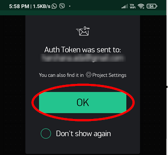
- After that, click “OK” and the Blynk app will email you the Auth Code
- Finally, you should receive an email from Blynk with the Authentication Code as shown below


Now you are ready with the basics. Next, we will set up the Voltage Display Button on the Blynk app.
On the Brink App, Touch the “+” button, then look for the “Value Display” on the item list under Displays. And Touch on it. Now change the values to 0 – 16. If you need to customize the display color of the text, there is an option for that as well. Also, you can name the button.
In addition to the above step guide checkout the Video for better Understanding.
There are many more options in the app, to display the voltage history or set notifications when the voltage drops than the desired value. But for the start you can only add one button with the free credit.
Programming your ESP8266 NodeMCU
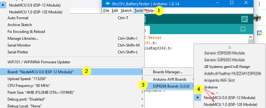
Also, Open Arduino application, select the board, details provided in the previous post.
Coding for the 0-16 Voltage Monitor
Here’s the full coding required for the Battery Voltage Monitor. The messages shown after double forward slash symbols describe the value provided. So you can change these if required. But if you select the same NodeMCU and the 0-25V sensor module, you don’t need to change anything other than the Auth Code and the Wi-Fi credentials.
#define BLYNK_PRINT Serial
#include <ESP8266WiFi.h>
#include <BlynkSimpleEsp8266.h>
// You should get Auth Token in the Blynk App.
char auth[] = “NwPLCOENRpAzUPvdeObWMj6Ez9yfW6I9”;
// Your WiFi credentials.
// Set password to “” for open networks.
char ssid[] = “Your Wi-Fi SSID – 2.4Ghz only”;
char pass[] = “Your Wi-Fi password”;
#include <SoftwareSerial.h>
int analogInput = A0;
float correctionfactor = 0; // here u adjust the correction if u need
float vout = 0.0;
float vin = 0.0;
float R1 = 30000; // here u must enter ur R1 value
float R2 = 7500; // here u must enter ur R2 value
int value = 0;
void setup() {
pinMode(analogInput, INPUT);
Serial.begin(9600);
Blynk.begin(auth, ssid, pass);
Blynk.virtualWrite(V6,vin);
}
void loop() {
value = analogRead(analogInput);
vout = (value * 3.3) / 1023.0;
vin = vout / (R2/(R1+R2));
vin = vin – correctionfactor;
Serial.print(“INPUT V= “);
Serial.println(vin,4);
Blynk.virtualWrite(V6,vin);
delay(1000); // by changing this value you can change the response
Blynk.run();
}
Copy and paste the above code to Arduino app and update your auth code and Wi-Fi settings
Next, test the code using the Verify button, as shown in the below screenshot.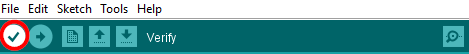
If there are no errors in the code, the result should show as “Done Compiling” on the green bar below.
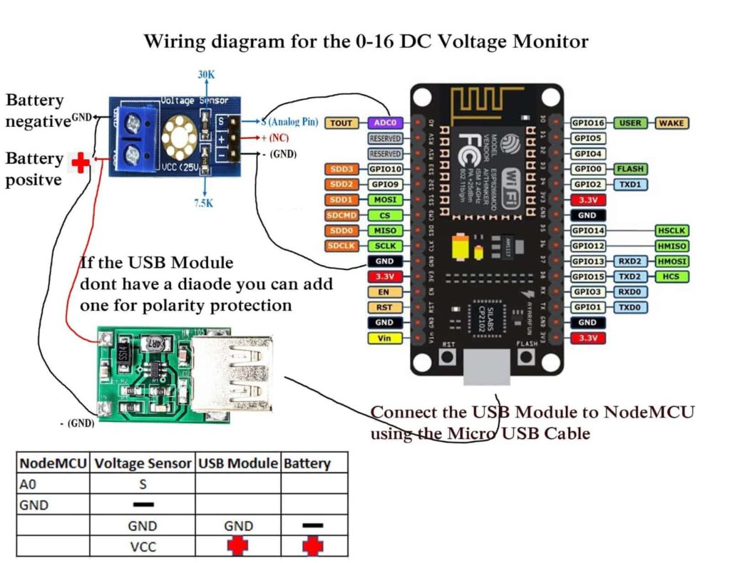
Wiring diagram for the DC Voltage Monitor
Also, I have shared an image of the wiring below. It is amazingly simple.
If you don’t like to use the Micro USB cable you can follow these steps provided below.
- Firstly, remove the USB female connector using the solder iron
- Also, look for the positive and negative connection usually it’s like shown in the image
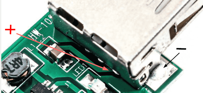
- Connect the – (negative) of the USB Module to NodeMCU GND (Any GND port is okay)
- Finally, Connect the + (positive) of the USB Module to Vin in the NodeMCU
Removing the Micro USB cable from the project saves some space. However, it will increase some work. like extra soldering.
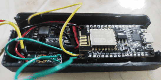
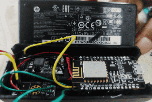
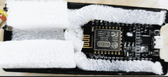
Here’s Some Images of My Voltage Monitor Project
Testing the Remote Voltage Monitor using Blynk App
Now it’s time to connect your Voltage Monitor to a Battery, to minimize the risk that could cause due to wiring errors it is better to provide a low voltage around 5 – 9V dc through a regulator. If you don’t have a regulator, use a few 4AA batteries. This is just for testing.
Once the battery is connected the ESP8266 module should connect to the Wi-Fi connection which was provided during the coding. This can be tested from the Blynk App.
If the device is connected, then the app indicator dot should show in Green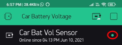
Once, everything is okay, then the voltage should show up in the Blynk App
Most importantly, if you see the readings that means you have successfully completed the project. If not, check the post from the beginning and troubleshoot what went wrong. If you still need support, contact me through comments. Also, make sure to follow the previous post if you are not clear about installing and setting up the Arduino application.
Please make sure to use all safety precautions when dealing with electricity.